Innovation activities
The technology of jet-breaking of the system of channels stimulating the filtration is implemented as follows:
- downhole assembly is run to the well on a production string; along with this while drilling a deflecting shoe is placed above the level of jet-breaking of deep filtration channels;
- operator from the control station turns on a drilling drive and drills the first hole in a casing string; the whole process of drilling is controlled by the operator at a wellhead;
- when drilling is completed, the drill is put in a transport position;
- operator from the control station turns the drilling block to a new position for drilling of a new hole;
- the required number of drilling cycles in a casing string is being completed; along with this the holes are located in one plane in a radial direction against the axis of a casing string;
- after completion of the last hole in a casing string the operator from the control station turns the electric engine of a turning and moving block and matches the exit channel of a deflecting shoe with the first drilled hole, controlling the whole process based on the data transmitted by the electronic block to the control station through the cable;
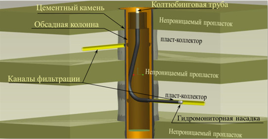
- a high-pressure hose fixed on a coiled tubing is lowered into a tubing string with a jet nozzle, which enters the hole, drilled in a casing string wall; the pump from the well head under pressure supplies a drill fluid to a jet nozzle through the coiled tubing and high-pressure hose and an extended filtration channel is created;
- after the filtration channel has been formed, high-pressure hose, fixed on the coiled tubing and a jet nozzle are removed from the filtration channel;
- operator from the well head turns the exit channel of a deflecting shoe to the next hole, drilled in a casing string, and jet breaks the new channel;
- necessary number of jet-breaking cycles is repeated in order to create a system of filtration channels;
- if necessary, after creation of the system of extended filtration channels in one plane at a set depth, the assembly with a tubing string and an anchor is moved inside the casing string within the boundaries of a pay bed and is set at the other depth.
The technology and the equipment for its implementation are protected by the Patent of the Russian Federation №2457318 and Eurasian patent №019699.
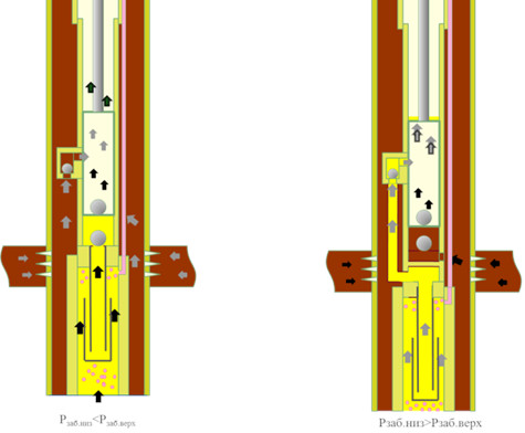
Formation fluid from the lower development object through the liner and a gas separator is delivered to a pump intake valve, and from the upper development object through the casing annulus to another pump intake valve. After the plunger has passed the second pump intake valve, the fluid from the development object with high pressure at pump suction comes to the cylinder. Inside the pump cylinder the fluids are mixed and lifted to the wellhead by a tubing string. Free gas from the lower horizon is transported from the gas separator through the gas outlet pipe to the well head.
Types of pumps used for dual completion by Production Association Belorusneft
| Identification | Pump type | Size, mm | Plunger size, mm | Running depth, up to, m | Used pipeline |
| TNO113-P TNO 113-О | Direct Reverse | 113 | 38 | 2400 | TG 7/16-25 TG 15/25-50 |
| 44 | 2100 | TG 7/16-25 | |||
| TNO 122-P TNO 122-О | Direct Reverse | 122 | 44 | 2100 | TG 7/16-25 TG 15/25-50 |
| TNO 133-P TNO 133-О | Direct Reverse | 133 | 57 | 1700 | TG 7/16-25 TG 15/25-50 |
Mass and size of pumps ТНО
|
Pump type |
Length, m | Body frame of side suction valve, mm | Mass, kg |
| TNO 113-P | 11.0 | 113 | 163 |
| TNO О113-О | 11.4 | 113 | 183 |
| TNO 122-P | 11.0 | 122 | 175 |
| TNO 122-О | 11.4 | 122 | 196 |
| TNO 133-P | 11.0 | 133 | 280 |
| TNO О133-О | 11.4 | 133 | 295 |
The recording cable head (RCH-42) for performing work in horizontal wells using coiled tubing allows you to:
- carry out production operations (tubing flushing, well development) and geophysical surveys using single coiled tubing, equipped with a geophysical cable;
- carry out inflow stimulation during geophysical well surveys with nitrogen injection into the CT;
- register collars of flow and production well strings, i.e. receive confirmation of the bottom hole landing without the involvement of geophysical party;
- monitor bottom hole parameters (depth, bottom hole pressure, bottom hole temperature) in real time;
- ensure cable integrity in an emergency.
RCH-42 consists of the following modules:
- module for tubing and cable fastening ensures connection of the RCH-42 to the CT, fixation of the geophysical cable;
- ealing module ensures sealing of geophysical cable cores;
- mergency disconnector ensures release of the tubing with a cable in case of geophysical instrument sticking;
- geophysical module ensures geophysical instrument attachment and transmission through the geophysical cable of bottom hole parameters determined by the instrument;
- production module ensures measurement and transmission of real-time bottom hole parameters (bottom hole pressure, bottom hole temperature, locator of tubing collars and production strings) with the possibility of fluid circulation, nitrogen injection through the CT.
Parameters are transmitted through the cable communication channel and transferred to the ground module, which ensures acceptance and recording of bottom hole parameters from the production module, as well as its power supply through the geophysical cable.
Also, the SkadScope software (developed by the Institute) is used to control and process the parameters.
Technical specifications of RCH-42
| Parameter | Value |
| Outside diameter | 42 mm |
| Length of the assembly with geophysical module | 950 mm |
| Length of the assembly with production module | 1350 mm |
| Number of geophysical cable cores | 1 |
| Maximum operating temperature | 120 °С |
| Maximum operating pressure | 50 MPa |
| Type of working agent | technical water, oil, gas-liquid mixture, nitrogen |
| Maximum fluid injection rate | 2,75 l/s |
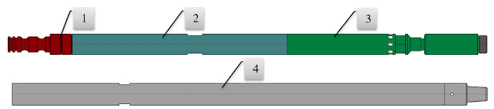
Recording cable head (RCH-42)
1 – module for tubing and cable fastening; 2 – sealing module, backpressure valve, disconnector; 3 – geophysical module; 4 – production module